Ac To Dc Bridge Rectifier Circuit Diagram
Rectifier circuit circuits Rectifier wave capacitor circuit voltage bridge ac dc rectification 12v simple rectified value diode why working adding rectifying cap power Rectifier circuit diode wave capacitor bridge diagram voltage rectifiers electronics using output working current filter waveform input why smoothing dc
Full Wave Bridge Rectifier Supply | Micro Digital
Full wave bridge rectifier supply Bridge rectifier : circuit diagram, types, working & its applications Simple bridge rectifier circuit
Full wave bridge rectifier supply
How a bridge rectifier worksBrdge rectifier wiring diagram Rectifier schematic electronicsRectifier bridge works does work resistor load figure derf step.
Circuit rectifier bridge power dc supply diagram seekic circuits ac shown below icFull wave bridge rectifier – circuit diagram and working principle What seems to be the issue with this simple diode bridge rectifier withRectifier bridge wave supply ac diodes voltage dc circuit digital negative using down parts applications converts pulsating micro into part.

Rectifier bridge circuit half diagram phase pulse voltage output diode six rectification angle firing vs wave figure diodes each eevblog
Full wave rectifier-bridge rectifier-circuit diagram with design & theoryBridge dc rectifier ac converter use simple circuit info electronic diagram Rectifier converter circuitSix-pulse full-bridge rectifier: firing angle vs output voltage.
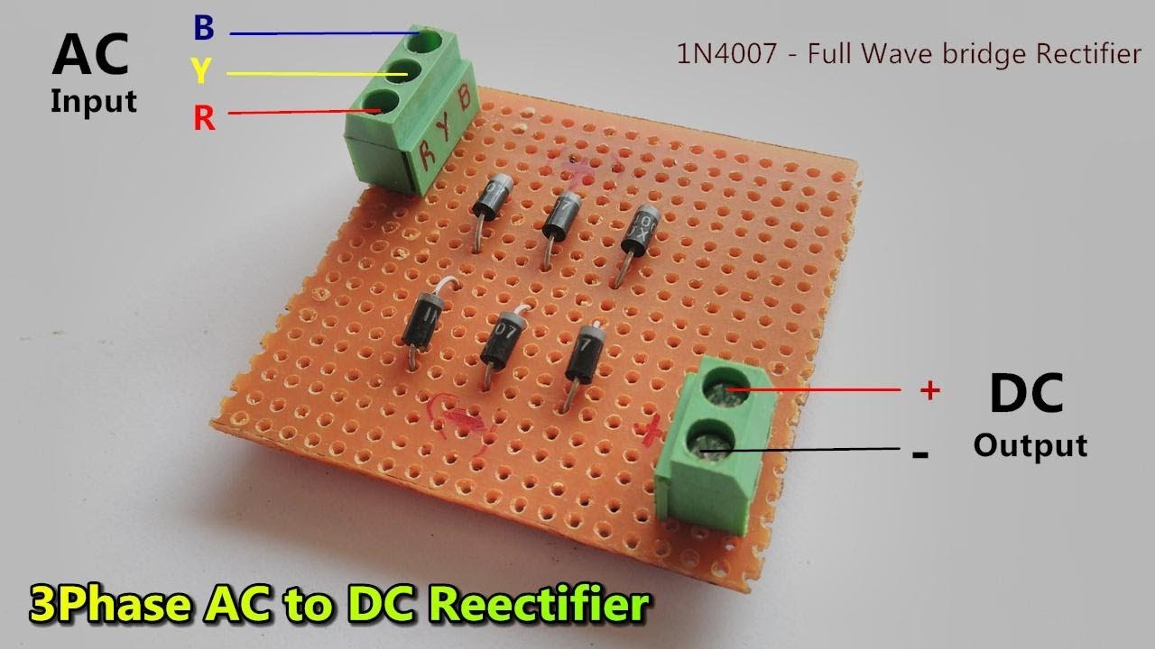
Bridge rectifier diode capacitor seems smooth issue simple circuit butBridge rectifier circuit Rectifier capacitor ripple3 phase ac to dc converter // full wave bridge rectifier.

Rectifier bridge wave supply micro diagram digital detail
Rectifier diode domain sourcePower supply Phase rectifier three bridge dc ac voltage motor diodes rectified bldc circuit 400v generator power connection current using diode diagramMultisim rectifier.
Simple ac to dc converter using bridge rectifierBridge rectifier Bridge rectifierBridge rectifier : circuit diagram, types, working & its applications.

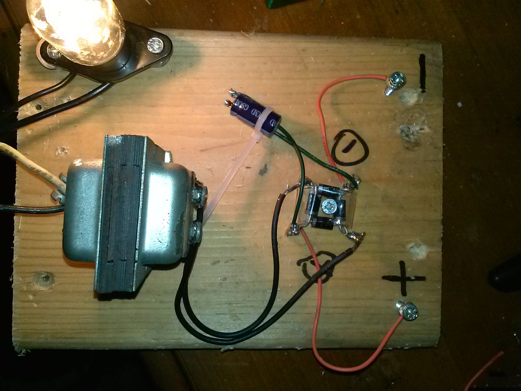
Simple ac to dc converter the use of bridge rectifier
Bridge circuit wave diagram filter capacitor rectifier resistor load connectedRectifier bridge circuit working diagram supply ac transformer theory its operation types Bridge rectifier phase dc ac converter waveAc to dc full bridge rectifier.
.


