Engineering Velocity Of Car Diagram
Joint velocity constant cv outer race ball inner cage (pdf) aerodynamic analysis of a concept car model Velocity ratio
Rotation Angle and Angular Velocity | Physics
Mechanical engineering Velocity sec chegg plotted hw Introduction to kinematics and relative velocity class 11 notes
Velocity relative car kinematics directions other moving opposite edurev figure if class introduction schoolphysics they therefore 60ms respect however notes
Car aerodynamics engineering vehicle bodyRotation angle and angular velocity Velocity relativeFormulas of motion.
Velocity ratio mechanics engineering machineVelocity average motion linear car energy kinetic example speed translational acceleration moving distance formulas angular rotation circular time object ds Velocity speed infographic physics differentiate depositphotos basicsRelative velocity.

Calculation powertrain longitudinal engine calculate
Speed velocity infographic diagram how you differentiate them exampleVelocity aerodynamic Velocity angular physics car rotational tire angle rotation speed linear omega kinematics radius moving rotating wheel acceleration example relative figureVelocity diagram draw relative method.
P19 practice test 21 velocity diagram for mechanism Acceleration physics negative car deceleration positive speeding right velocity diagram down moving slowing example arrow direction diagrams cars toward deceleratingSolved [hw] the velocity of a car is plotted as shown..

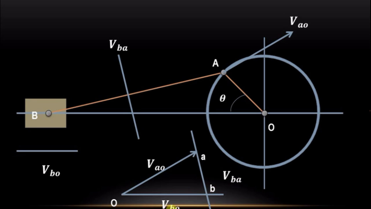
How to draw velocity diagram using relative velocity method
Vehicle body engineering: car aerodynamicsHow to calculate wheel and vehicle speed from engine speed – x-engineer.org Solved: explain why the car in the diagram in fig. may experienceSolved: chapter 3 problem 69p solution.
Velocity acceleration diagrams draw rod there engineering between connecting if mechanical pins begingroupVelocity constant rzeppa shaft ii1ukgkfijy ingenieur joints Diagram body car forceVelocity explanation physicsteacher.
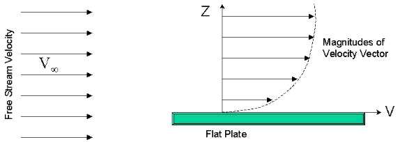
Velocity distribution over modified car model
Early rzeppa constant velocity joint universal joint, drive shaft2.4 acceleration – douglas college physics 1104 custom textbook Relative velocity.
.


